Post by schercheeroo on Jan 13, 2018 21:04:20 GMT
I've been playing with the closed loop boost controller on the MS2 for a while now and I've formed the conclusion that its not very good.
In fact I would say it doesn't work (or at least I can't make it work repeatedly), and the few people I've spoken to on the subject have given similar feedback.
In my experiance I'm seeing different boost in each gear, over boost on throttle stabs, over boost on pulls to red line from low RPM, changes in boost when the weather changes. Hardly what I would call 'control'.
I've looked at the data in an effort to try and understand the limitations of the MS2's boost controller, and I have some ideas I think are worth discussion.
--------------------------------------------------------
MS2 closed loop boost control overview
--------------------------------------------------------
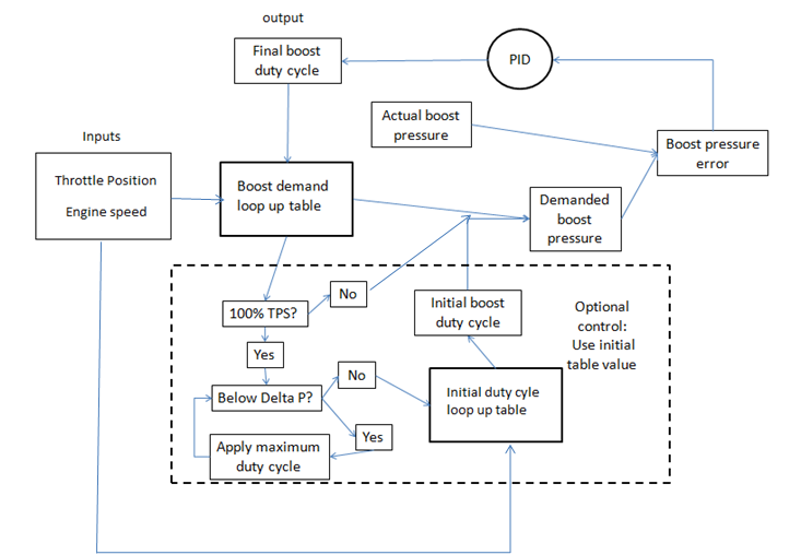
In its simplest form the level of boost is requested via a 3d loop up table (map) that uses throttle position and RPM on the X and Y axis with manifold air pressure on the Z axis.
The boost is controlled by adjusting the duty cycle of a solenoid value that bleeds boost out of the turbo wastegate actuator can.
And that's it.
On the software side the MS2 compares the requested boost value to the actual boost value and uses a PID to try and bring the difference between them to zero. This feedback loop is the only thing controlling the boost.
There is the option to use an initial duty cycle table which gives the PID a value to start from, but after the PID starts it makes up its own values.
I believe this is the why the closed loop boost control fails to control properly. There are no limits on the PID and no feed foward loops on the controller to force the PID to produce sensible values.
It'll happily run away and produce an over boost condition.

--------------------------------------------------------
TPS & RPM based model - No temperature compensation
--------------------------------------------------------
I think this is the major down fall of the MS2's closed loop boost control. The strategy requests a manifold pressure based on engine speed and throttle position.
The issue with this method of control is that air density changes with temperature.
For a constant engine speed and manifold pressure the amount of air going into the engine on a cold day will be greater than the air flow on a hot day as the air is denser when its cold.
A more robust method would have been to reference the manifold pressure to mass air flow and not engine speed. This would mean any changes in air temperature (and therefore air density) are compensated for.
The MS2 already computes the mass air flow as part of the speed density calculation that it uses to work out the fueling needs of the engine so this really would not have been difficult to implement.
--------------------------------------------------------
Boost correction - PID feedback and lack of feedforward
--------------------------------------------------------
The MS2s boost correction is poor. At least in my experience. I find the PID terms will just bugger off and do as they please because there is no way of constraining them.
The only way I have found to avoid boost spikes is to set the PIDs super slow, the result is generally under boosting or slow response. In which case I see no benefit to the closed loop control over the open loop control.
At least with open loop the boost duty cycle is well constrained and you can be sure of what its doing.
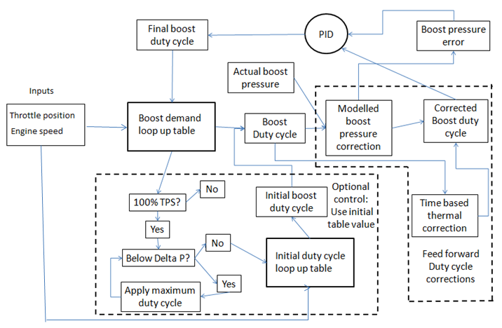
A more robust solution would be to provide the majority of the P term by comparing the actual boost pressure to a modeled boost pressure.
I would implement a strategy that is a mix of the current open and closed loop strategy. The boost demand set by a TPS and mass air flow map. The boost duty cycle would then calculated from a demanded boost pressure and mass air flow map.
An inverted version of this table (Boost duty cycle on the X axis, Mass air flow on the Y axis, with manifold air pressureon the Z axis) would be used as a feedforward term and let the boost controller workout which way to adjust the boost duty cycle to get to the requested boost pressure.
--------------------------------------------------------
Thermal inertia - why boost is different in every gear
--------------------------------------------------------
The final point I'd like to raise is that of the boost being different in every gear. This makes defining the PID terms very tricky as you're trying to hit a target that changes every time you shift up a cog.
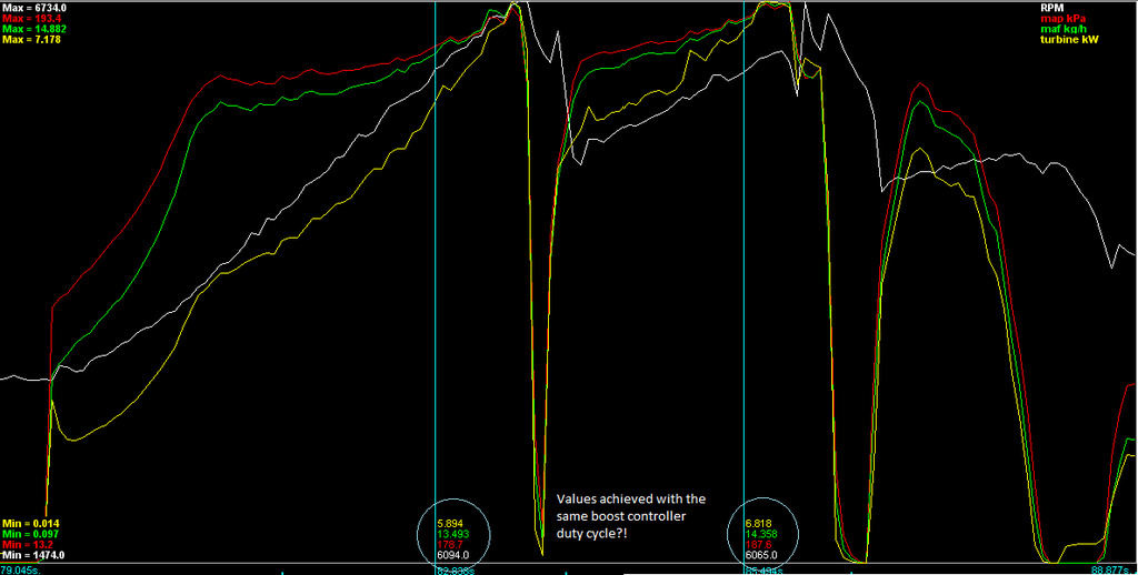
Check out the graph below, I've calculated the engine mass air flow, and I made a guess the amount of work being done by the turbine from my turbine in temperature sensor.
The graph shows a 3ed and 4th gear pull. Look at the yellow line (turbine power) you can see when the car starts to accelerate the thermal energy actually drops because the heat in the exhaust gas is being used to heat up the turbine housing, turbine wheel, exhaust manifold etc. The result is less energy available to drive the turbine up to speed.
The MS2 makes no attempt to compensate for this which leads to slower than optimal spool time.
After the change from 3ed to 4th the turbo is up to temperature and the boost is much higher even though the boost duty cycle (not shown on the graph) is the same. This must be due to the turbo producing more work as its hotter.
A better way to handle this would be to have all the maps above produced at steady state conditions fully heat soaked, then during a transient the strategy would apply a correction to the boost duty cycle based on a time based temperature at the turbine inlet.


In fact I would say it doesn't work (or at least I can't make it work repeatedly), and the few people I've spoken to on the subject have given similar feedback.
In my experiance I'm seeing different boost in each gear, over boost on throttle stabs, over boost on pulls to red line from low RPM, changes in boost when the weather changes. Hardly what I would call 'control'.
I've looked at the data in an effort to try and understand the limitations of the MS2's boost controller, and I have some ideas I think are worth discussion.
--------------------------------------------------------
MS2 closed loop boost control overview
--------------------------------------------------------
In its simplest form the level of boost is requested via a 3d loop up table (map) that uses throttle position and RPM on the X and Y axis with manifold air pressure on the Z axis.
The boost is controlled by adjusting the duty cycle of a solenoid value that bleeds boost out of the turbo wastegate actuator can.
And that's it.
On the software side the MS2 compares the requested boost value to the actual boost value and uses a PID to try and bring the difference between them to zero. This feedback loop is the only thing controlling the boost.
There is the option to use an initial duty cycle table which gives the PID a value to start from, but after the PID starts it makes up its own values.
I believe this is the why the closed loop boost control fails to control properly. There are no limits on the PID and no feed foward loops on the controller to force the PID to produce sensible values.
It'll happily run away and produce an over boost condition.

--------------------------------------------------------
TPS & RPM based model - No temperature compensation
--------------------------------------------------------
I think this is the major down fall of the MS2's closed loop boost control. The strategy requests a manifold pressure based on engine speed and throttle position.
The issue with this method of control is that air density changes with temperature.
For a constant engine speed and manifold pressure the amount of air going into the engine on a cold day will be greater than the air flow on a hot day as the air is denser when its cold.
A more robust method would have been to reference the manifold pressure to mass air flow and not engine speed. This would mean any changes in air temperature (and therefore air density) are compensated for.
The MS2 already computes the mass air flow as part of the speed density calculation that it uses to work out the fueling needs of the engine so this really would not have been difficult to implement.
--------------------------------------------------------
Boost correction - PID feedback and lack of feedforward
--------------------------------------------------------
The MS2s boost correction is poor. At least in my experience. I find the PID terms will just bugger off and do as they please because there is no way of constraining them.
The only way I have found to avoid boost spikes is to set the PIDs super slow, the result is generally under boosting or slow response. In which case I see no benefit to the closed loop control over the open loop control.
At least with open loop the boost duty cycle is well constrained and you can be sure of what its doing.
A more robust solution would be to provide the majority of the P term by comparing the actual boost pressure to a modeled boost pressure.
I would implement a strategy that is a mix of the current open and closed loop strategy. The boost demand set by a TPS and mass air flow map. The boost duty cycle would then calculated from a demanded boost pressure and mass air flow map.
An inverted version of this table (Boost duty cycle on the X axis, Mass air flow on the Y axis, with manifold air pressureon the Z axis) would be used as a feedforward term and let the boost controller workout which way to adjust the boost duty cycle to get to the requested boost pressure.
--------------------------------------------------------
Thermal inertia - why boost is different in every gear
--------------------------------------------------------
The final point I'd like to raise is that of the boost being different in every gear. This makes defining the PID terms very tricky as you're trying to hit a target that changes every time you shift up a cog.
Check out the graph below, I've calculated the engine mass air flow, and I made a guess the amount of work being done by the turbine from my turbine in temperature sensor.
The graph shows a 3ed and 4th gear pull. Look at the yellow line (turbine power) you can see when the car starts to accelerate the thermal energy actually drops because the heat in the exhaust gas is being used to heat up the turbine housing, turbine wheel, exhaust manifold etc. The result is less energy available to drive the turbine up to speed.
The MS2 makes no attempt to compensate for this which leads to slower than optimal spool time.
After the change from 3ed to 4th the turbo is up to temperature and the boost is much higher even though the boost duty cycle (not shown on the graph) is the same. This must be due to the turbo producing more work as its hotter.
A better way to handle this would be to have all the maps above produced at steady state conditions fully heat soaked, then during a transient the strategy would apply a correction to the boost duty cycle based on a time based temperature at the turbine inlet.


 le sigh